PXL Controller Installation Guide
1.0 Introduction
This document contains basic information for the installation of the PXL-500 Controller.
2.0 Important Note:
Keri Public Statement on the Amazon Key
Keri does not support the use of the Amazon Key on Keri controllers. The Amazon Key does not interface to Keri products in a way that allows the Building Owner or Manager to maintain complete control over their system, nor does it provide any tracking information on when the Amazon Key was used to open a door. The addition of the Amazon Key to a site introduces a security degradation beyond the control of Keri's access control system.
Neither Keri nor Amazon provides any documentation on how an installer would integrate the Amazon Key with Keri's access control system. Because of this, Keri has strong concerns about the knowledge of the Amazon Key installers as evidenced by the damage Amazon Key installers have caused to Keri controllers and installations at multiple sites. Any Keri controller failure caused by the installation of an Amazon Key device is cause for voiding the controller warranty. Keri cannot be held responsible for any security lapses created by the use of the Amazon Key. |
3.0 Product Specifications
3.1 Unit Dimensions
• PXL-500/PXL-510 controller PCB
- 6.75 inches high by 6.00 inches wide by 1.75 inches deep, including wiring connectors
- (17.15 cm by 15.25 cm by 4.45 cm)
• PXL-500/PXL-510 controller PCB with an LCD-1 Alpha/Numeric Display
- 7.70 inches high by 6.00 inches wide by 1.75 inches deep, including wiring connectors
- (19.60 cm by 15.25 cm by 4.45 cm)
• PXL-500/PXL-510 controller PCB with an SB-593 Satellite Board
(with or without an LCD-1 Alpha/Numeric Display)
- 7.25 inches high by 6.00 inches wide by 1.75 inches deep, including wiring connectors
- (18.45 cm by 15.25 cm by 4.45 cm)
• Enclosure
- 13 inches high by 9 inches wide by 4 inches deep - (33.02 cm by 22.86 cm by 10.16 cm)
• Operating Temperature/Humidity Range
- 0°F to 140°F (-18°C to 60°C)
- 0% to 90% Relative Humidity, non-condensing
3.2 Controller Power Requirements
• 12 VDC @ 1 A
Output Relay Contact Rating
• 1 Amp @ 24 VDC
3.3 Input Device Configuration - 3 Inputs
• Door Sense - normally closed
• Request to Exit - normally open
• Global Unlock - normally open, or Auxiliary RTE A-Door - normally open 3.4 Controller Memory Retention
• 5 year lithium battery back up to support controller RAM and real-time clock
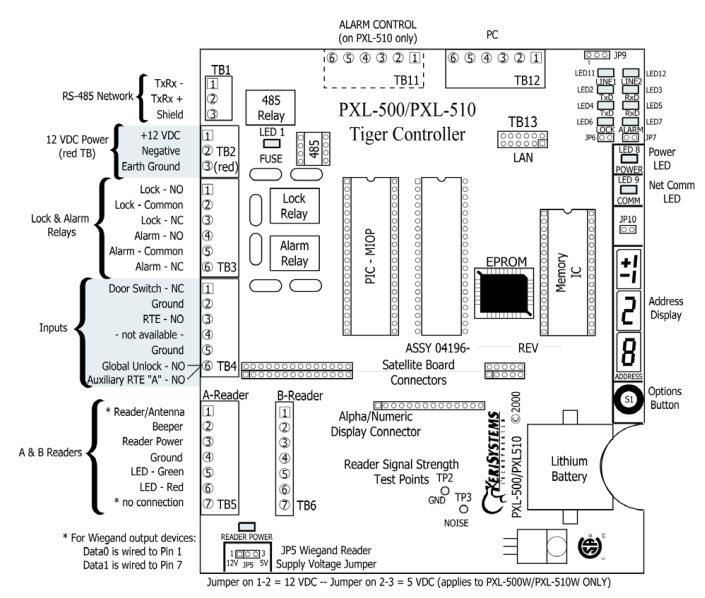
4.0 PXL-500 Controller Wiring
This document contains basic information for the installation of the PXL-500 Controller.
Notes:
It is the responsibility of the installation organization to have only technically qualified personnel performing the installation.
5.0 Controller LED Definitions
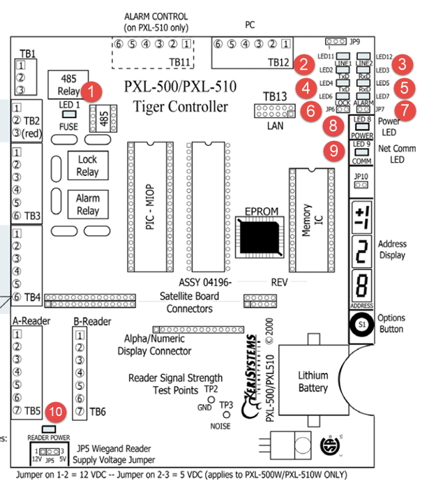
- LED 1 - Power fuse LED - It will be red if the controller's power and ground lines are reversed.
- LED 11 and LED 12 - RS-485 network continuity test LEDs.
- LED 2 and LED 3 - Data transmit and receive LEDs (Serial connection not supported in Borealis).
- LED 4 and LED 5 - Secondary data transmit and receive LEDs - Not Used.
- LED 6 - Lock LEDs - Solid green to indicate if the lock relay is active.
- LED 7 - Alarm LED - Solid green to indicate if the alarm relay is active.
- LED 8 - Solid green to indicate the controller is receiving correct power. Solid red to indicate the power is incorrect.
- LED 9 - RS-485 comms LED - Flashes green when the primary controller is communicating with secondary controllers.
- LED 10 - Wiegand reader power LED - Solid red to indicate that the reader port is set to output 12v (only applies to a PXL-500W).
6.0 Wiring Instructions
6.1 Terminal Blocks

Note: Screws on terminal blocks must be tightened securely.
6.2 Connecting the Earth-Ground and the 12VDC Power

6.3 Controller Earth-Grounding
To ensure optimum earth-grounding of the controller and its connected peripherals, you should make a quality earth-ground connection to the metal enclosure lug (which displays an adjacent earth-ground symbol).
This good-quality, earth-ground at the enclosure lug will provide an earth-ground for the entire enclosure - and will therefore ground anything that is connected to; the metal enclosure, the four metal screws at each corner of the PCB, plus, through circuitry on the PCB, this includes anything connected to the lug marked J6 or pin 3 of the TB10 power connector.
In addition, the enclosure itself must be earth grounded to a good quality ground point, external to the enclosure for a complete path to ground.
Also, the shield/drain wire of any reader cables MUST be terminated to one of the following points - any corner screw attaching the controller to the enclosure, Pin 3 of TB10 or the ground lug of the enclosure.
7.0 Cable Requirements
7.1 RS-485 Network Cable
- two conductor, shielded, twisted pair, stranded, AWG 24 wire (Belden 9501 or a larger gauge).
- 16,000 feet total network length.
Notes:
When wiring the RS-485 terminal block connector, be sure to use the small 3-pin connector provided.
RS-485 cabling should be installed away from high voltage systems. Fluorescent lights always cause issues with low-voltage systems, especially when the ballast is old and starts to become noisy/lights blinking might introduce unnecessary voltage spikes on our data communication line (RS485 lines), which can make our transmitted data corrupted.
7.2 Input Power
- two conductor, stranded, AWG 18 wire (Belden 8461 or a larger gauge)
- 200 foot maximum length for systems using an SB-293 with two readers
Note: On long power cable runs, the cable resistance causes a drop in voltage at the end of the cable run. Be sure your power supply does provide 12 VDC at the end of the cable run.
7.3 Earth Ground
- Single conductor, AWG 18 wire (or a larger gauge)
7.4 Keri Systems Proximity Readers
- six conductor, shielded, stranded, AWG 24 wire (Belden 9536 or a larger gauge).
- four conductor, shielded, stranded, AWG 24 wire (Belden 9534 or a larger gauge) for the MS-4000 only (there is no beeper or LED in the MS-4000).
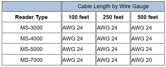
7.5 Wiegand Compatible Readers
- four to seven conductor, shielded, stranded, wire – depending upon the Wiegand reader’s requirements.
- a minimum gauge of AWG 24 is required for data transfer with a 500-foot maximum run length per Wiegand specification.
7.6 Input and Output Connections
- two conductor, stranded, AWG 22 (or a larger gauge)
Notes:
- The lock output relay may require a heavier gauge of wire depending upon the current demands of the lock and the length of the lock wiring run.
- If plenum cable is required, please reference the Belden plenum equivalent to the cables listed above.
8.0 Reader Connections
The PXL-500W controller can be configured to accept input from single-line LED, dual-line LED, and Essex keypad Wiegand input devices.
Note: The Wiegand Reader must transfer data according to the Security Industry Association's Wiegand Reader Interface Standard (document number AC-01D-96). Keri Systems, Inc. cannot guarantee the performance or reliability of Wiegand Readers that do not meet these data transfer guidelines.
IMPORTANT NOTE: All Keri Systems proximity readers use 12VDC power while some Wiegand-compatible readers use 5VDC power. Check your reader's power requirements and verify jumper JP5 is set correctly - JP5 is located beneath the TB5 reader port.
- The "A" reader is wired to TB5.
- The "B" reader is wired to TB6.
8.1 MS Reader Wiring
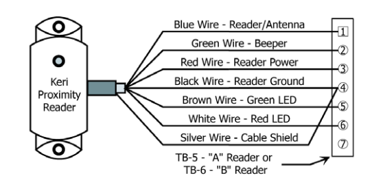
8.2 Wiegand Reader Wiring
For single-line LED readers, the LED wire connects to pin 6, there is no LED wire on pin 5.
For dual-line LED readers, the red LED is wired to pin 6 and the green LED line is wired into pin 5.
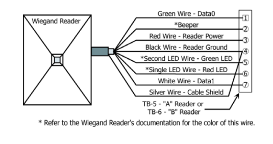
Note: The wire colors called out in the above image are industry standard wire colors. However, some manufacturers may not follow these industry standard designations. Before installation, please refer to the Wiegand device’s manual to see if the device’s wire colors follow the industry standard. If not, then match the wire’s purpose to the call outs shown here.
9.0 Connecting a Door Status Input
Each PXL-500/PXL-510 is shipped with an installation kit including all necessary terminal blocks and transorbs. One of these terminal blocks has a jumper across pins 1 and 2. This terminal block is designated for use on TB-4. If a door switch is not used on the controller, this jumper prevents a continuous door open status alarm from being received by the controller. If a door switch is used, simply remove this jumper and install the door switch leads.
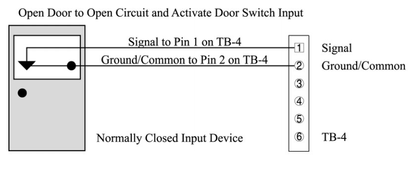
Note: A Door Switch must be installed on any door to which anti-passback is being applied for proper tracking of the anti-passback feature.
10.0 Connecting a Request to Exit (RTE) Input
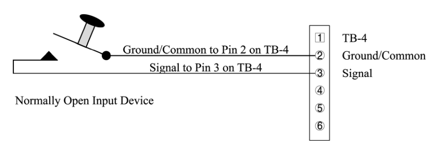
The RTE circuit is a normally-open circuit. Press the button to close the circuit and activate the RTE A-door input.
11.0 Connecting a General Purpose Input
The general-purpose input is used in conjunction with the programmable input/output feature of Borealis. There are three possible uses for the general-purpose input.
• the primary controller may be figured for either Site Unlock or Auxiliary A-door RTE
• the PXL secondary unit may be figured for Auxiliary A-door RTE only
Connecting a Site Unlock Input

Connecting an Auxiliary A-door RTE input

12.0 Connecting an Alarm Output Relay
13.0 Connecting a Lock
13.1 Connecting a Fail-Safe Lock

13.2 Connecting a Fail-Secure Lock

13.3 Using Transorbs
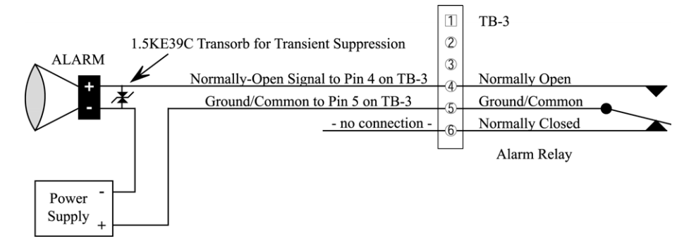
The PXL-500 ship-kit includes 1.5KE39C transorbs for suppressing transients generated by the lock. These transorbs should always be installed across any electric device attached to a controller output, especially a lock, such as a maglock. The transorbs should be installed as close to the lock as possible (as displayed in the previous two images) - not at the controller.
Note: The transorbs have no polarity and so can be installed in either orientation.
14.0 RS-485 Access Control Network Wiring
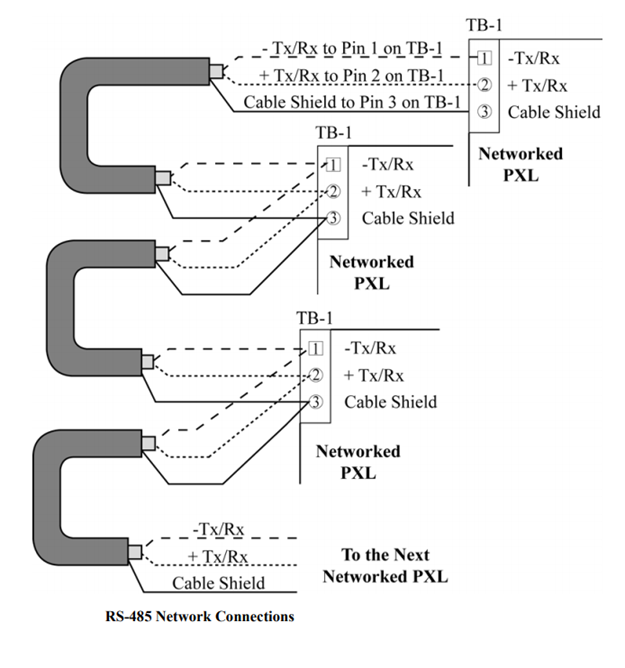
Communication between the primary PXL and the secondary PXL controllers is via an RS-485 linear data line. The data line is daisy-chained in and out of the TB1 port located in the top left corner of the PCB. The cable type for this RS-485 network is a single pair (shielded, stranded and twisted). Belden 9501 is the recommended cable type as it provides the most protection again sources of electrical interference (EMI).
- The maximum total network length is 16,000 feet/4000m.
- The network topology must be a 'daisy-chain' configuration - but you can have multiple spurs connected to the TB1 port of the primary controller.
- You do not need to connect the RS-485 shield to the controller's earth-ground connection - this is done automatically through a circuit on the controller (when the controller is addressed as #1).
15.0 Connecting the PXL Primary Controller
15.1 Via a LAN-520 Ethernet Module
Use of a LAN-520 to provide LAN/WAN Ethernet connectivity between Borealis and one or more PXL networks.
Note: When using a LAN-500 for ethernet communication, the jumpers across JP6 and JP7 must be removed for communication.
For instructions about how to add the controller to the Borealis software, please refer to the PXL Setup Guide.
17.0 Powering the Controller for the First Time
Notes:
- Verify the earth ground has been connected at pin 3 of TB-2 before turning the power on for the first time.
- Do not connect the 12 VDC power supply’s terminal block output to the TB-2 connector on the PXL-500/PXL-510 controller until you have completed the following steps.
17.1 Verify the 12 VDC Supply Voltage
- Set the DVM to a DC volt scale capable of reading 12 VDC.
- Turn the power supply ON.
- Place the Red DVM lead on the power supply’s terminal block output - Pin 1.
- Place the Black DVM lead on the power supply’s terminal block output - Pin 2.
- Check the DVM reading. It should read between +12 VDC to +14 VDC.
- If the DVM does not read between +12 VDC to +14 VDC, verify the power supply is of the correct voltage, verify the cable length does not exceed 200 feet, and verify the cable gauge is AWG 18. This problem must be corrected before power can be supplied to the controller.
- Turn the power supply OFF.
- Connect the power supply’s terminal block output to the TB-2 connector on the PXL-500/PXL-510 controller.
- The controller is now ready to be powered ON.
Note: On long power cable runs, keep in mind the resistance in the cable itself causes a drop in voltage at the end of the run. The power supply must be able to account for this voltage drop.
18.0 Resetting the Controller's RAM
If you're turning system power on for the first time or have just changed the EPROM/PIC, the PXL-500/PXL-510 controller's RAM must be reset before performing any other action. This clears any spurious information that may be in the RAM in preparation for entering your access control information.
- Before applying power, insert a jumper across pins 1 and 2 of JP10 on the controller.
- Hold the S1 Options Button down and turn the controller's power on.
- Continue to hold down the S1 options button for at least 10 seconds.
- The beeper for the reader attached to the controller will beep as power comes on followed by a beep-beep indicating the controller's firmware has reset the controller's RAM.
- Release S1. If the optional Alpha/Numeric Display has been installed, it will display a “SYSTEM RESET” message.
- Turn system power off and remove the jumper on JP10.
- The controller is now ready to be powered up and receive information from Borealis.
IMPORTANT NOTE: Resetting the system RAM completely erases all information within the PXL-500/PXL-510 controller. If there is any information in system RAM from an access control installation and the system RAM is reset, the information in the controller is lost and cannot be recovered.
19.0 Set the Controller's Address
By default, the controller will be set to address #1 (this configures the controller as the primary controller). If you wish to set the controller as a secondary controller (address #2 up to #128) you will need to change the controllers address. Controllers do not need to be added to the network in consecutive order, the only requirement is that each controller on the network has a unique address.
- To set the desired operating address for the controller, verify the jumper to JP10 is NOT installed (if the jumper on JP10 is installed, the controller RAM will be reset when the power is turned on).
- Hold the S1 Options Button down and turn the controller's power on.
- Continue to hold down s1 button for at least 10 seconds after power has been applied.
- The beeper for the reader attached to the controller will beep as power comes on. Release S1.
- The address display LEDs then become active and the controller's address can be set. If an Alpha/Numeric Display is connected to the controller, “ADDRESS CHANGE” will appear on the display.
- The address range is from 1 to 128 (the primary controller must be set to address 1).
- Quickly double clicking S1 toggles between increasing and decreasing the controller address. The top LED character will display either a "+" or a "-" to show which direction is active. A single click of S1 changes the controller address by 1. If you're at address 128, a +1 click will roll the address over to 1; conversely, if you're at address 1 a -1 click will roll the address over to 128.
- Holding S1 down rapidly scrolls through the addresses.
- After the new address has been set, you must wait approximately 30 seconds after releasing the S1 button. There is a timer in the controller's firmware that assumes that after 30 seconds of inactivity (no address clicks), the entered address is the desired address for that controller.
- When the 30-second timer expires, there will be a beep-beep-beep from the reader indicating the controller has recognized and accepted the new address and the address LEDs will turn off. If an Alpha/ Numeric Display is connected to the controller, “UNIT ##” will appear on the display (where ## is the controller's address).
- To ensure the address change will be recognized by Borealis, power down the controller. Then, after verifying the JP10 jumper is NOT installed (installing the JP10 jumper will reset the controller RAM when powering up), apply power to the controller.
- The controller is now ready to be used with the new address.
Note: When the controller’s address is changed, the RAM is automatically reset. A Sync must then be performed from the software.
Related Articles
Entraguard Controller Setup in Borealis
1.0 How Do I Add an Entraguard Controller? The following document explains how to setup an Entraguard controller in Borealis. Once a PXL (and Entraguard) hub has been claimed and auto-updated, you can then add an Entraguard primary controller or you ...KB Controller Installation Guide
Borealis KB Controller Installation Guide (attached)PXL Controller Settings
1.0 Introduction The following document explains the PXL controller settings that are available and editable in Borealis. From the main menu, go to Hardware >> Controllers. The controllers page will appear. From the Actions drop-down list on the ...Add a PXL Primary Controller to Borealis
1.0 How Do I Add a PXL Controller? Once the PXL-configured hub has been claimed and updated, you can then add a PXL primary controller. A PXL primary is the first controller on the network (and is address #1). There are two methods for adding a PXL ...KB Controller - Full Setup Guide
KB Controller Full Setup Guide (attached)